我们使用机器学习技术将英文博客翻译为简体中文。您可以点击导航栏中的“中文(简体)”切换到英文版本。
亚马逊云科技 数据中心内互连的持续改进模型
这篇博文介绍了我们在构建 亚马逊云科技 网络基础设施时做出的一些技术管理和硬件决策。我们与网络工程师合作撰写了这篇博客,以揭示为客户提供 亚马逊云科技 服务而在幕后进行的一些工作。本博客特别探讨了我们在追求比现成行业标准设备更高的可靠 性和容量时
概述
亚马逊云科技 网络在全球范围内大规模运营。作为最大的云服务提供商,我们经常需要解决规模和复杂性很少有人考虑过的网络挑战。在过去的 17 年中,亚马逊云科技 已迅速从弗吉尼亚州的一个地点扩展到 全球
2018 年,在容量规划期间,我们意识到网络的庞大规模以及客户发送的数据量,因此我们必须从 100 GbE 迁移到 400 GbE 光学元件,以保持领先于需求。从迁移到 100GbE 开始,过去的经验也告诉我们,更高的数据速率产品相应地会有更高的故障率。亚马逊云科技 的核心宗旨是确保网络所有层级的冗余,而且我们已经能够最大限度地减少并基本消除硬件故障对客户造成的任何直接影响。但是,当我们为过渡到400 GbE做准备时,我们意识到这种部署将比前几代复杂得多。复杂性的增加以及更高的数据速率意味着有可能出现复杂情况,从而增加故障率并给我们的网络带来压力。有鉴于此,我们改变了互连方法,以确保其质量符合我们的标准,并提供客户所依赖的可用性。在这篇博客文章中,我们将解释 亚马逊云科技 如何为数据中心中的数千万个互连建立持续改进模型,并成功扭转数据速率上升的故障率上升的趋势。
亚马逊云科技 互连的演变
光学互连是数据中心和电信网络的关键组件,允许将数据移动到需要的地方。它们在带有集成激光器和探测器的收发器之间连接光纤电缆,探测器能够发射和接收光信号。从历史上看,亚马逊将光纤互连视为商品,依赖制造收发器光学器件和电缆的供应商根据行业标准对其产品进行验证。这在很大程度上反映了其他超大规模企业和云提供商的传统方法,因为标准化这些产品并使其尽可能地互换,有助于简化我们用于运行数据中心的操作和工具,并降低总体成本。尽管这种方法多年来一直行之有效,但在部署一代 100 千兆以太网 (GbE) 期间,我们必须做出基于可靠性的设计决策,逐步降低链路预算的利润,而链路预算的利润率本来是基于商品的方法取得成功的。尽管从表面上看,减少幅度似乎很小,但由于我们有数千万个互连,我们看到了真正而持续的影响。这将带来一系列新的挑战,需要大量投资来缓解和解决。
在400 GbE生成之前,光学互连通过NRZ(不归零)编码提供所需的带宽,其中有两个不同的级别(编码为 0 或 1)以特定的信令速率驱动。例如,为了实现 100 GbE,我们在四根光纤或四个波长上组合了一个 25 GbE 信号,总带宽为 100 GbE。为了达到 400 GbE,我们不仅需要将信号速率从 25 GbE 提高到 100 GbE,还必须将编码更改为 PAM4(4 级脉冲振幅调制),从而将电平提高到 4(编码为 00、01、10 或 11)。编码的这种变化使每一次数据脉冲都能携带更多的比特,从而传送更多的信息。您可以在图 1 中的信号眼图中看到数据速率和编码的变化以及由此产生的额外复杂性。信号眼图表示 x 轴上的时间和 y 轴上的功率水平。信号电平之间的转换会产生类似于一对轨道之间的一系列眼睛的图案。为了应对这种额外的复杂性,我们需要额外的组件来帮助清理和维护信号,以便在传输客户数据时尽可能减少错误和丢包。
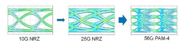
图 1。10G/25G NRZ 的两个不同功率等级与 56G PAM-4 的四个不同功率等级之间的差异显而易见
支持 400 GbE 互连的关键组件之一是 DSP(数字信号处理器),DSP 位于交换机专用集成电路 (ASIC) 和可插拔光学器件的发射和接收 OE(光学引擎)之间。当我们转向更高的波特率(调制速率或每单位时间的信号变化次数)时,100GbE 模块一代中使用的传统模拟重定时器无法提供足够的灵活性和性能来补偿电气和光学通道中额外的复杂性。DSP通过获取模拟高速信号并将其转换为数字域来对此进行改进,在数字域中,我们可以使用多种关键工具应用信号处理来清理和改善数据流。这提供了更好的均衡、反射消除和功率预算。它引入了更先进的接收器架构,例如最大似然序列探测器 (MLSD),这是一种从噪声数据流中提取有用数据的数学算法。它还使添加前向误差校正 (FEC) 成为可能,从而增加了冗余信号,允许自动校正错误。实现所需的链路性能取决于涉及大量参数的详细而复杂的校准过程。DSP 和模块固件 (FW) 负责找到这些最佳设置,并使用复杂的校准算法,这是业界首次部署这些算法。
这项技术本身不仅增加了我们互连的复杂性,而且我们实现供应链多元化的愿望也增加了。由于我们的机队规模庞大和供应限制,我们发现有必要使用多个供应商。我们需要这种多样性,不仅需要模块和系统层面,还需要关键子组件,例如DSP和交换机ASIC。即使在 COVID-19 疫情加剧了供应链问题的情况下,我们也能够提前规划供应商冗余意味着我们能够确保部署足够的容量来满足客户的需求。但是,实现健康的供应链会使网络中的互操作性变得更加复杂,如图 2 所示,交换机、模块及其关键子组件(如 DSP 和 ASIC)上的多个供应商创建了可能的链路配置的庞大矩阵。技术和互操作性复杂性相结合是一个重大风险,我们必须采取行动加以解决。
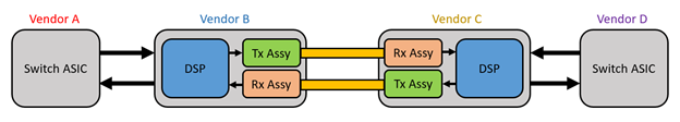
图 2. 400 GbE 链路显示了维护来自多个供应商的组件互操作性的复杂性
定义互连的持续改进模型
由于模块及其固件的复杂性不断增加,我们知道我们必须以与以前不同的方式在 亚马逊云科技 部署 400 GbE 互连。我们必须提高响应数据中心需求的速度,而不是将这些互连视为在出现故障时直接更换的商品。这促使我们建立了一个模型,该模型可以实现互连的持续改进周期,如图 3 所示。
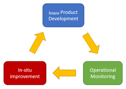
图 3。互连生命周期持续改进模型
该模型跟踪我们的互连生命周期,从 亚马逊云科技 的产品开发过程到供应商在我们网络中的整个产品运营过程中。这要求我们完成多项举措,这些举措不仅使我们能够在收发器仍安装在机队中时对其进行就地升级,从而持续降低400 GbE互连的故障率,而且还要运用机队的经验并改进我们的产品开发流程。
我们的第一步是在光学可插拔产品的开发中发挥更深层次的作用。通常,我们依靠电气电子工程师协会 (
为了确保纸面要求能够真正提高性能和质量,我们不能仅仅停留在定义标准上,而必须与供应商一起在产品开发中发挥主导作用。这意味着不仅要致力于组件和系统设计,还要主动确保产品按照我们的设计运行。这包括在我们自己的实验室中评估他们的初始原型,并就如何改进产品向供应商提供直接指导。这还意味着在极端情况和加速条件下测试生产线分布的长尾巴,以确保部署到机队的所有产品都符合我们数据中心部署的要求。为了确保其可扩展性和长期性,我们建立了多种机制,使他们交付的每个零件都能继续符合我们的标准。我们为预生产过程和生产线本身增加了几个门,使我们能够跟踪和监控模块性能。根据不断变化的需求、机队的新信息或供应商的反馈,为了确保我们的测试尽可能全面,我们不断对其进行改进。例如,我们增加了几项环境测试和更严格的测试条件,而这些条件在当时是典型的行业测试方法所没有涵盖的。这些机制确保我们尽早发现机队中出现的问题,并使我们能够调整产品开发流程以快速响应不断变化的需求。
架构基于 亚马逊云科技 服务的监控系统
为了了解我们是否通过定义新规格来提高产品质量,我们必须关闭反馈循环。我们需要测量数千万个模块在机群中的实际性能。为此,我们建立了运营监控服务,以跟踪部署到网络中的产品时的性能。
我们使用您熟悉的 亚马逊云科技 服务构建了这个基础设施,并通过我们正在监控的互连网络与之通信。我们在图 4 中显示了一个简化的服务图。
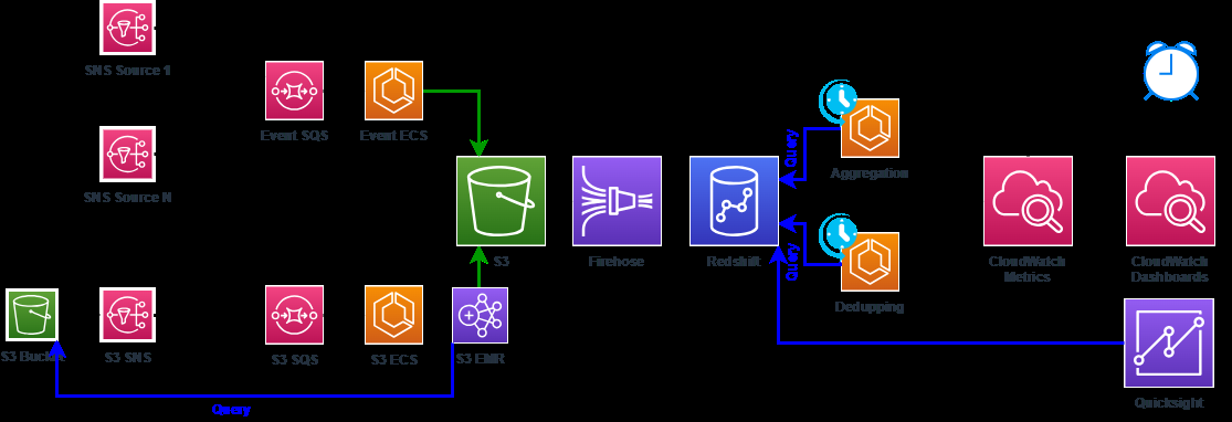
图 4。互连监控服务基础设施图
首先,我们通过亚马逊
值得注意的是,我们的内部团队使用与任何 亚马逊云科技 客户相同的服务。像任何其他客户一样,我们一直在寻求提高效率并以可扩展的方式运营。例如,我们最初使用
我们的监控系统使 亚马逊云科技 能够在整个生命周期中跟踪数百万个 400 GbE 互连。这包括收集、采集和警报以下来源的数据:供应商的工厂和生产线,设备进入我们的网络时的部署工具日志,跟踪机队运营绩效的监控和修复机制,以及在退役设备上运行的分析得出的实验室测试结果。
我们与供应商合作,提高了测量和数据收集的行业标准。这包括收集额外的关键性能指标 (KPI),例如预先的 FEC BER(误码率),这使我们能够在超过 FEC 阈值之前检测到信号降低。通过根据该指标采取行动,我们可以防止数据包丢失和收到的数据中出现可能对客户造成影响的错误。我们与供应商合作,在其收发器中实施了
为我们的内部和外部客户提供更高的可靠性
有了监控和跟踪机队性能并创建反馈回路的能力,我们现在必须根据收集的大量信息采取行动。因此,我们设定了就地或生产中改进互连的目标。我们必须创建机制来提高模块的质量,这些模块在运行和承载客户流量期间,以及仍在进行认证或生产线上的模块。这些机制包括当我们使用新建立的监控系统检测到特定的故障模式时触发的机制,以及在整个机队中定期推送到生产阶段的活动。结合起来,这些流程帮助我们不断提高互连质量的标准。这对于我们已经开始部署的复杂 400 GbE 一代互连来说是最重要的。
我们在网络中观察到的质量改善反映了这种新的互连方法和我们开发的工具的功效。如图 5 所示,与使用旧版本的模块相比,运行最新老式固件的 400 GbE 模块之间的链路故障率提高了 4 到 5 倍。这种巨大的差异表明我们是对的:400 GbE 一代互连的复杂性增加要求我们改变做事方式。尽管由于 亚马逊云科技 网络中内置了大量冗余,链路故障很少对客户造成实际影响,但减少故障对于维持客户所需的网络容量和减轻网络工程师的运营负担至关重要。
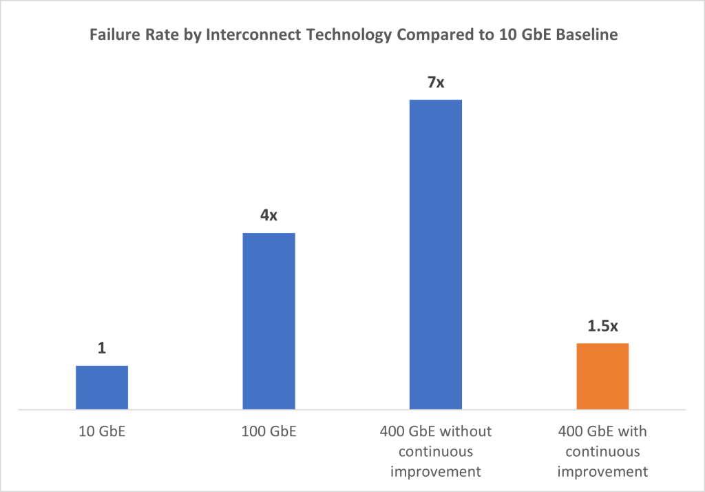
图 5。亚马逊云科技 队列中各技术的互连链路故障率性能比较
在 亚马逊云科技,我们很自豪地说,通过每一代互连技术,我们成功地扭转了整个行业性能下降的趋势。实际上,400 GbE一代的链路故障率已经低于100 GbE的链路故障率,实际上已接近10 GbE的链路故障率。这是一项重大成就,只有通过我们实施的机制和流程才有可能实现,这些机制和流程使我们能够更密切地监控和提高 400 GbE 互连产品的可靠性。在开发下一代 800 GbE 互连及更高版本的过程中,我们将继续利用和增强这些流程,以便我们可以进一步延长正常运行时间,并尽可能快速、无错误地向客户交付数据。

余保罗
Paul 是亚马逊网络服务的网络开发经理。他在网络产品开发组织从事光纤互连方面的工作,专注于构建和维护保持 亚马逊云科技 数据中心运转的技术、工具和系统。

Al Hayder
Al 是亚马逊网络服务的首席网络开发工程师。他在网络产品开发组织工作,专注于实现尖端的可扩展网络技术。

Poorya Saghari
Poorya 是亚马逊网络服务的高级网络开发经理。他在网络产品开发组织工作,专注于推动尖端技术扩展支持 亚马逊云科技 网络的互连解决方案。

伊波利塔斯·杜纳拉维奇
Ipolitas 是 亚马逊云科技 网络和安全服务的技术营销负责人。Ipolitas 拥有 15 年以上的营销经验,在 亚马逊云科技 工作了 4 年以上,负责推出许多在 亚马逊云科技 网络基础设施上运行的托管网络服务和功能。
*前述特定亚马逊云科技生成式人工智能相关的服务仅在亚马逊云科技海外区域可用,亚马逊云科技中国仅为帮助您发展海外业务和/或了解行业前沿技术选择推荐该服务。